RTC
RTC Demo Code Support List
This chapter introduces the details of the RTC demo code.
RTC Demo for Comparator Function
The description of RTC demo code 1 is shown in the following table.
Demo 1 |
|
|---|---|
Sample Purpose |
Demonstrate RTC comparator function. |
File Path |
|
Function Entry |
|
Expected Result |
Print string rtc_handler in Debug Analyzer every 1536ms. |
RTC Demo for Overflow Function
The description of RTC demo code 2 is shown in the following table.
Demo 2 |
|
|---|---|
Sample Purpose |
Demonstrate RTC count overflow function. |
File Path |
|
Function Entry |
|
Expected Result |
For RTL87x3D, |
RTC Demo for Tick Function
The description of RTC demo code 3 is shown in the following table.
Demo 3 |
|
|---|---|
Sample Purpose |
Demonstrate RTC tick function. |
File Path |
|
Function Entry |
|
Expected Result |
|
RTC Demo for Calendar Function
The description of RTC demo code 4 is shown in the following table.
Demo 4 |
|
|---|---|
Sample Purpose |
Demonstrate RTC calendar functionality. |
File Path |
|
Function Entry |
|
Expected Result |
|
RTC Demo in Power Down Mode
The description of RTC demo code 5 is shown in the following table.
Demo 5 |
|
|---|---|
Sample Purpose |
Demonstrate RTC work in power down mode. |
File Path |
|
Function Entry |
|
Expected Result |
|
Functional Overview
RTC is an independent timer. RTC has a set of continuous counting counters to provide a calendar clock. It can be converted into the current time and date of the system by querying the counter value.
Feature List
32KHz clock source.
24-bit read-only counter (RTL87x3E and RTL87x3EP), 32-bit read-only counter (RTL87x3D).
12-bit prescaler.
Support 4 comparator interrupts.
Support overflow interrupt, indicating that the counter overflows and wraps around to 0.
Support tick interrupt.
Support wake-up system from low power mode.
Support 8 comparators.
4 comparators can only be used to trigger wake-up.
Program Examples
Comparator Function Operation Flow
RTC comparator function initialization flow is shown in the following figure.
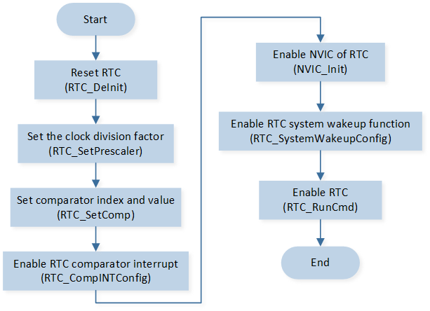
RTC Comparator Function Initialization Flow Chart
The codes below demonstrate the RTC comparator function initialization flow.
void driver_rtc_init(void)
{
   RTC_DeInit();
   RTC_SetPrescaler(RTC_PRESCALER_VALUE);
   RTC_SetComp(RTC_COMP_INDEX, RTC_COMP_VALUE);
   RTC_MaskINTConfig(RTC_INT_CMP_1, DISABLE);
   RTC_CompINTConfig(RTC_INT_CMP_1, ENABLE);
   RamVectorTableUpdate(RTC_VECTORn, RTC_Handler);

   /* Configure RTC interrupt */
   NVIC_InitTypeDef NVIC_InitStruct;
   NVIC_InitStruct.NVIC_IRQChannel = RTC_IRQn;
   NVIC_InitStruct.NVIC_IRQChannelPriority = 3;
   NVIC_InitStruct.NVIC_IRQChannelCmd = ENABLE;
   NVIC_Init(&NVIC_InitStruct);

   /* Start RTC */
   RTC_SystemWakeupConfig(ENABLE);
   RTC_RunCmd(ENABLE);
}
RTC interrupt handle flow is shown in the following figure.
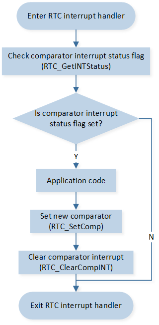
RTC Interrupt Handle Flow Chart
The codes below demonstrate the RTC interrupt handle flow.
void rtc_handler(void)
{
   IO_PRINT_TRACE0("rtc_handler");
   if (RTC_GetINTStatus(RTC_INT_CMP_1) == SET)
   {
      RTC_SetComp(RTC_COMP_INDEX, RTC_GetCounter() + RTC_COMP_VALUE);
      RTC_ClearCompINT(RTC_COMP_INDEX);
   }
}
Overflow Function Operation Flow
RTC overflow function initialization flow is shown in the following figure.
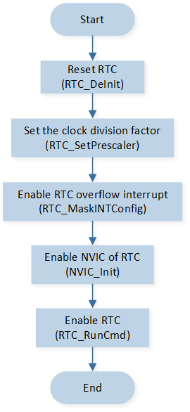
RTC Overflow Function Initialization Flow Chart
The codes below demonstrate the RTC overflow function initialization flow.
void driver_rtc_init(void)
{
   RTC_DeInit();
   RTC_SetPrescaler(RTC_PRESCALER_VALUE);
   RTC_MaskINTConfig(RTC_INT_OVF, DISABLE);

   RamVectorTableUpdate(RTC_VECTORn, rtc_handler);

   /* Config RTC interrupt */
   NVIC_InitTypeDef NVIC_InitStruct;
   NVIC_InitStruct.NVIC_IRQChannel = RTC_IRQn;
   NVIC_InitStruct.NVIC_IRQChannelPriority = 2;
   NVIC_InitStruct.NVIC_IRQChannelCmd = ENABLE;
   NVIC_Init(&NVIC_InitStruct);

   /* Start RTC */
   RTC_RunCmd(ENABLE);
}
RTC interrupt handle flow is shown in the following figure.
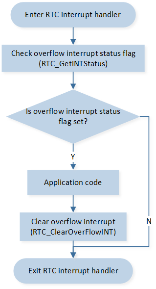
RTC Interrupt Handle Flow Chart
The codes below demonstrate the RTC interrupt handle flow.
void rtc_handler(void)
{
   /* RTC overflow interrupt handle */
   if (RTC_GetINTStatus(RTC_INT_OVF) == SET)
   {
      // Add application code here

      RTC_ClearOverFlowINT();
   }
}
Tick Function Operation Flow
RTC tick function initialization flow is shown in the following figure.
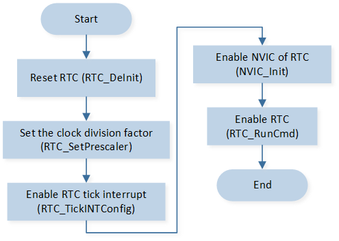
RTC Tick Function Initialization Flow Chart
The codes below demonstrate the RTC tick function initialization flow.
void driver_rtc_init(void)
{
   RTC_DeInit();
   RTC_SetPrescaler(RTC_PRESCALER_VALUE);
   RTC_MaskINTConfig(RTC_INT_TICK, DISABLE);
   RTC_TickINTConfig(ENABLE);

   RamVectorTableUpdate(RTC_VECTORn, rtc_handler);

   /* Config RTC interrupt */
   NVIC_InitTypeDef NVIC_InitStruct;
   NVIC_InitStruct.NVIC_IRQChannel = RTC_IRQn;
   NVIC_InitStruct.NVIC_IRQChannelPriority = 2;
   NVIC_InitStruct.NVIC_IRQChannelCmd = ENABLE;
   NVIC_Init(&NVIC_InitStruct);

   /* Start RTC */
   RTC_RunCmd(ENABLE);
}
RTC interrupt handle flow is shown in the following figure.
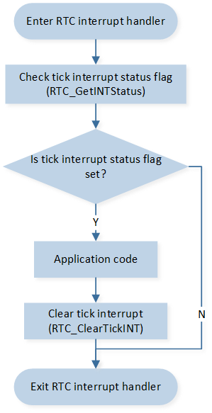
RTC Interrupt Handle Flow Chart
The codes below demonstrate the RTC interrupt handle flow.
void rtc_handler(void)
{
   /* RTC overflow interrupt handle */
   if (RTC_GetINTStatus(RTC_INT_TICK) == SET)
   {
      // Add application code here

      RTC_ClearTickINT();
   }
}