IO General Introduction
The document primarily introduces an overview of the IO demo application, covering its requirements, configurations, compilation and download procedures, experimental verification, code overview, and project structure. IO demo project shows how to use peripherals to communicate with other devices. A specific peripheral and its usage scenario can be changed to demonstrate, with its source files added to the build target and its demo functions called in main(). The document offers a detailed and comprehensive guide, covering every aspect from environment setup to code implementation, to help developers quickly get started with and test the IO demo application.
Requirements
The sample supports the following development kits:
Hardware Platforms |
Board Name |
Build Target |
|---|---|---|
RTL87x3E EVB |
|
|
RTL87x3D HDK |
RTL87x3D EVB |
|
RTL87x3EP HDK |
RTL87x3EP EVB |
|
Note
To purchase EVB, please visit https://www.realmcu.com/en/Home/Shop.
When built for an xxx_2M_xxx build target, the sample is configured to compile and run with a 2M flash map.
When built for an xxx_4M_xxx build target, the sample is configured to compile and run with a 4M flash map.
When built for an xxx_16M_xxx build target, the sample is configured to compile and run with a 16M flash map.
To quickly set up the development environment, please refer to the detailed instructions provided in Quick Start.
Configurations
Users can modify the macro definitions shown below in the sample code to configure the pins used in the example.
#define UART_TX_PIN         P3_1
#define UART_RX_PIN         P3_0
#define UART_CTS_PIN        P0_0
#define UART_RTS_PIN        P0_1
For specific pin definitions, please refer to the list below:
Building and Downloading
The detailed information about building and downloading can be found in Building and Downloading.
This sample can be found under board\evb\io_demo in the SDK folder structure.
Take the project rtl87x3e_io_demo.uvprojx and target io_demo_16M_bank0 as an example, to build and run the sample with the keil development environment. Follow the steps listed below:
Open
rtl87x3e_io_demo.uvprojx.Choose the build target
io_demo_16M_bank0.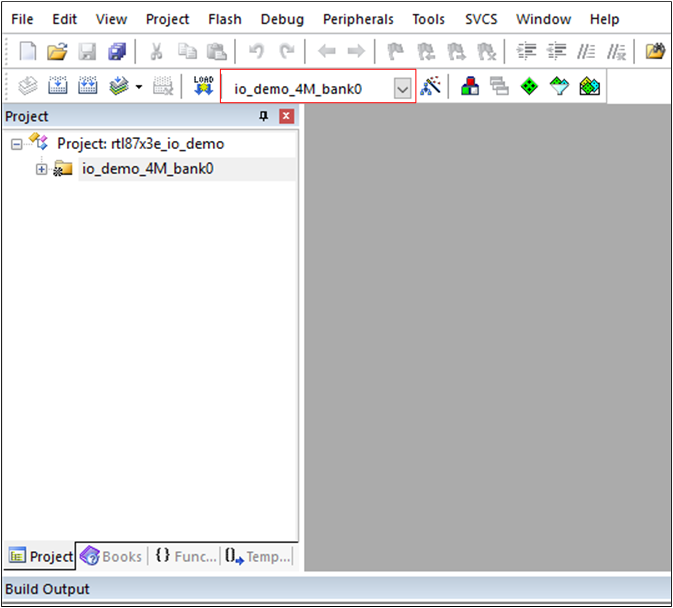
Choose Build Target
Build the target.
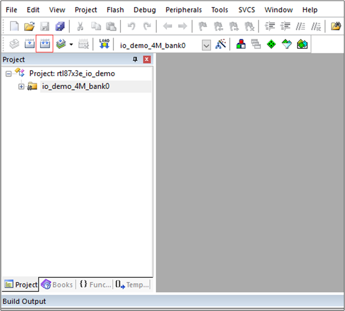
Building
After a successful compilation, the APP bin file
io_demo_bank0_MP-v0.0.0.0-xxx.binwill be generated in the directorybin\rtl87x3e\flash_16M\bank0.Download the generated APP bin
io_demo_bank0_MP-v0.0.0.0-xxx.bininto the EVB board.Press the Reset button on the EVB board.
Experimental Verification
The detailed test procedure can be found in the list below:
Code Overview
The IO demo application overview will be introduced according to the following parts:
The IO demo project overview will be introduced in the chapter Source Code Directory.
The IO demo project source code overview will be introduced in the chapter Source Code Overview.
Source Code Directory
This section describes the project directory and project structure. The reference files directory is as follows:
Project directory:
board\evb\io_demo.Project source code directory:
src\sample\io_demo.
Source files in the sample project are currently categorized into several groups as below:
└── Project: io_demo_16M_bank0
    ├── include                          ROM UUID header files. Users do not need to modify it.
    ├── lib                              Includes all binary symbol files that user application is built on.
    ├── cmsis                            The cmsis source code. Users do not need to modify it.
    ├── io_driver                        The IO driver code. Users do not need to modify it.
    ├── io_hal                           The IO HAL layer code. Users do not need to modify it.
    ├── app                              The application source code.
    ├── adc                              The ADC demo source code.
    ├── gdma                             The GDMA demo source code.
    ├── gpio                             The GPIO demo source code.
    ├── i2c                              The I2C demo source code.
    ├── ir                               The IR demo source code.
    ├── keyscan                          The KeyScan demo source code. RTL87x3EP doesn't support it.
    ├── led                              The LED demo source code.
    ├── lpc                              The LPC demo source code.
    ├── qdec                             The QDEC demo source code.
    ├── rtc                              The RTC demo source code.
    ├── sdio                             The SDIO demo source code.
    ├── spi                              The SPI demo source code.
    ├── spi3w                            The 3-wire SPI demo source code. Only RTL87x3D supports it.
    ├── tim                              The TIMER and PWM demo source code.
    ├── uart                             The UART demo source code.
    ├── ctc                              The CapTouch demo source code. Only RTL87x3E supports it.
    ├── i2s                              The I2S demo source code.
    ├── dlps                             The DLPS demo source code.
    ├── canbus                           The CAN demo source code. Only RTL87x3EP supports it.
    └── spi_external_flash               The SPI external flash demo source code.
Source Code Overview
This section describes some parts of the source code used in the application of this project.
Initialization
The main function is invoked when the application is powered on or the chip is reset, and it performs the following initialization functions:
RAM_TEXT_SECTION
int main(void)
{
   __enable_irq();
   WDG_Disable();

   IO_PRINT_INFO0("Hello io demo !");

   extern void gpio_int_demo(void);
   gpio_int_demo();

   os_sched_start();
}
The gpio_int_demo() function can be replaced by the demo entry function in the demo files, such as adc_demo() in the adc_demo.c file. Note that each demo entry function is independent of each other.
Initialization Flow
Peripheral initialization mainly consists of the following components:
Set peripheral PINMUX and PAD.
Enable peripheral clock signal.
Set peripheral initialization parameters.
Enable peripheral.
The initialization procedure is shown in the following figure, where ‘XXX’ is the name of the peripheral to be initialized, such as GPIO, I2C, or SPI.
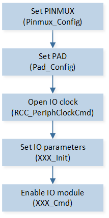
IO Initialization Flow
Clock Configuration
Enable GPIO clock by calling RCC_PeriphClockCmd() function.
RCC_PeriphClockCmd(APBPeriph_GPIO, APBPeriph_GPIO_CLOCK, ENABLE);
PINMUX Configuration
Configure PINMUX status of the pin by calling Pinmux_Config() function.
/* Configure Pin P0_5 as GPIO function */
Pinmux_Config(P0_5, DWGPIO);
For optional pin values and map GPIO please reference the file below:
RTL87x3E:
inc\rtl87x3e\platform\rtl876x.hRTL87x3D:
inc\rtl87x3d\platform\pin_def.hRTL87x3EP:
inc\rtl87x3ep\platform\pin_def.h
PAD Configuration
Configure the PAD status of the pin by calling Pad_Config() function.
Pad_Config(P0_5, PAD_PINMUX_MODE, PAD_IS_PWRON, PAD_PULL_NONE, PAD_OUT_ENABLE, PAD_OUT_HIGH);
Interrupt Configuration
Enable IRQ interrupt by calling NVIC_Init function.
NVIC_InitTypeDef NVIC_InitStruct;
NVIC_InitStruct.NVIC_IRQChannel = GPIO5_IRQ;
NVIC_InitStruct.NVIC_IRQChannelPriority = 5;
NVIC_InitStruct.NVIC_IRQChannelCmd = ENABLE;
NVIC_Init(&NVIC_InitStruct);
Initialize Peripheral
Initialize the peripheral by calling XXX_Init for each peripheral, and XXX is the name of the peripheral to be initialized.
GPIOx_Init();
Disable Peripheral
Disable the peripheral by calling XXX_DeInit for each peripheral, and XXX is the name of the peripheral to be disabled.
GPIOx_DeInit();