SPI Master RGB Write
This document introduces three SPI communication samples. The samples demonstrate how SPI uses one data line to control an LED in three different modes: polling (sample1), interrupt (sample2), and DMA (sample3). In all three examples, the SPI is configured as a master, the clock is set to 10MHz, the direction is full-duplex, and the data frame size is 12 bits. The chip writes RGB data to the SPI slave to light up the LED.
Requirements
For hardware requirements, please refer to the Requirements.
Wiring
Connect P1_0 (SPI master MOSI) to the LED controller.
The hardware connection of SPI sample code is shown in the figure below.
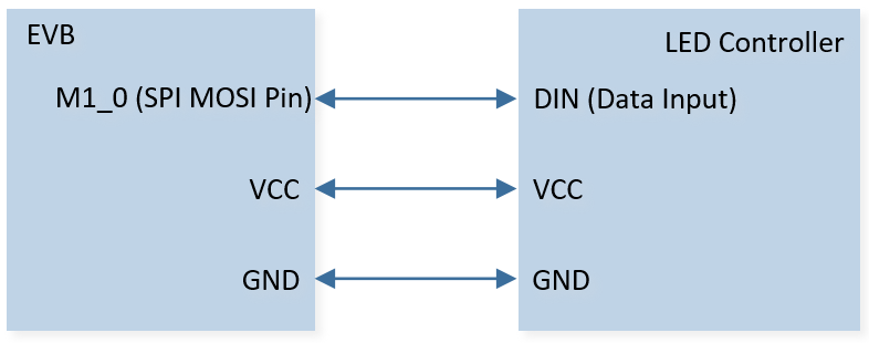
SPI Sample Code Hardware Connection Diagram
SPI Communication for RGB LED Control
This sample uses the WS2812B specification as an example to demonstrate how to light up the LED controller using SPI single-wire communication.
RGB data consists of 24 bits, with every 8 bits corresponding to green, red, and blue from high to low order, as shown in the figure below. By adjusting the RGB data, the LED can display different colors. The data is sent from the high bit first, following the GRB sequence. For example:
0xa50000: LED lights up green.
0x00a500: LED lights up red.
0x0000a5: LED lights up blue.

Composition of 24bit RGB Data
Based on the definitions of the ‘0’ code and ‘1’ code signal timing in the LED specification, RGB data needs to be converted to SPI data for transmission through SPI MOSI. When SPI CLK is set to 10MHz, the transmission speed is 0.1 us/bit. For example, the data transmission timing settings for the ‘0’ code and ‘1’ code are as follows:
‘0’ code: high level time (T0H) + low level time (T0L) = 0.3 + 0.9 us = 1.2 us.
‘1’ code: high level time (T1H) + low level time (T1L) = 0.9 + 0.3 us = 1.2 us.
Therefore, the SPI data frame to be sent should be 12 bits, and the data conversions for ‘0’ code and ‘1’ code are 0xE00 and 0xFF8 respectively.
Signal Name |
Signal Description |
Duration |
Tolerance |
|---|---|---|---|
T0H |
0 code, high voltage time |
0.4us |
±150ns |
T1H |
1 code, high voltage time |
0.85us |
±150ns |
T0L |
0 code, low voltage time |
0.85us |
±150ns |
T1L |
1 code, low voltage time |
0.4us |
±150ns |
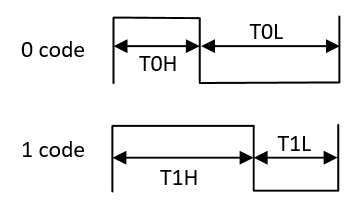
Sequence Chart of WS2812B LED
Configurations
-
The following macros can be configured to modify pin definitions.
#define PIN_SPI_MOSI P1_0
-
The entry function are as follows, call this function in
main()to run this sample code. For more details, please refer to the Initialization.For sample 1, use the following entry function:
spi_rgb_polling_demo();
For sample 2, use the following entry function:
spi_rgb_interrupt_demo();
For sample 3, use the following entry function:
spi_rgb_dma_demo();
Building and Downloading
For building and downloading, please refer to the Building and Downloading.
Experimental Verification
Sample 1 Verification
Press the Reset button on the EVB, convert
rgb_dataintoSPI_WriteBufin preparation for sending.Send
SPI_WriteBufwith a data length of 91 to LED controller.
Sample 2 Verification
Press the Reset button on the EVB, convert
rgb_dataintoSPI_WriteBufin preparation for sending.-
Send
SPI_WriteBufwith a data length of 24 to LED controller. When the data length in TX FIFO is equal to or below its threshold value, trigger theSPI_INT_TXEinterrupt and prints log.spi_tx_handler: SPI TX FIFO Empty
Sample 3 Verification
Press the Reset button on the EVB, convert
rgb_dataintoSPI_WriteBufin preparation for sending.-
Send
SPI_WriteBufwith a data length of 24 to LED controller. When completing the transmission, it enters the GDMA interrupt and prints log.spi_tx_dma_handler
Code Overview
Source Code Directory
For all three samples, please refer to the Source Code Directory for the project directory.
Sample 1 source code:
Source code directory:
sdk\src\sample\io_demo\spi\polling\spi_rgb_polling_demo.c.
Sample 2 source code:
Source code directory:
sdk\src\sample\io_demo\spi\interrupt\spi_rgb_interrupt_demo.c.
Sample 3 source code:
Source code directory:
sdk\src\sample\io_demo\gdma\spi_dma\spi_rgb_dma_demo.c.
RGB Polling Initialization Flow
The initialization flow for peripherals can refer to Initialization Flow.
The SPI initialization flow can refer to SPI Initialization Flow Chart.
-
Call
Pad_Config()andPinmux_Config()to initialize the SPI MOSI pin.static void board_spi_init(void) { Pinmux_Config(PIN_SPI1_MOSI, SPI1_MO_MASTER); Pad_Config(PIN_SPI1_MOSI, PAD_PINMUX_MODE, PAD_IS_PWRON, PAD_PULL_NONE, PAD_OUT_ENABLE, PAD_OUT_HIGH); }
Call
RCC_PeriphClockCmd()to enable the SPI clock and function.-
Initialize the SPI peripheral:
Define the
SPI_InitTypeDeftypeSPI_InitStructure, and callSPI_StructInit()to pre-fillSPI_InitStructurewith default values.Modify the
SPI_InitStructureparameters as needed. The SPI initialization parameter configuration is shown in the table below.Call
SPI_Init()to initialize the SPI peripheral.
SPI Initialization Parameters SPI Hardware Parameters
Setting in the
SPI_InitStructureSPI
Direction
Device Role (SPI Master or SPI Slave)
Data Frame Size
Clock Polarity
Clock Phase
Clock Div
4
Frame Format
Call
SPI_Cmd()to enable SPI.
RGB Interrupt Initialization Flow
The initialization flow for peripherals can refer to Initialization Flow.
The SPI initialization flow can refer to SPI Initialization Flow Chart.
-
Call
Pad_Config()andPinmux_Config()to initialize the pins.static void board_spi_init(void) { Pinmux_Config(PIN_SPI1_MOSI, SPI1_MO_MASTER); Pad_Config(PIN_SPI1_MOSI, PAD_PINMUX_MODE, PAD_IS_PWRON, PAD_PULL_NONE, PAD_OUT_ENABLE, PAD_OUT_HIGH); }
Call
RCC_PeriphClockCmd()to enable the SPI clock and function.-
Initialize the SPI peripheral:
Define the
SPI_InitTypeDeftypeSPI_InitStructure, and callSPI_StructInit()to pre-fillSPI_InitStructurewith default values.Modify the
SPI_InitStructureparameters as needed. The SPI initialization parameter configuration is shown in the table below.Call
SPI_Init()to initialize the SPI peripheral.
SPI Initialization Parameters SPI Hardware Parameters
Setting in the
SPI_InitStructureSPI
Direction
Device Role (SPI Master or SPI Slave)
Data Frame Size
Clock Polarity
Clock Phase
Clock Div
4
Frame Format
Transmit FIFO Threshold Level
0
Call
NVIC_Init()to enable NVIC of SPI.Call
SPI_Cmd()to enable SPI.
RGB DMA Initialization Flow
The SPI RGB DMA initialization flow requires first initializing the SPI peripheral, followed by TX DMA initialization. The SPI initialization flow can refer to SPI Initialization Flow Chart. The SPI TX DMA initialization flow can refer to SPI TX DMA Initialization Flow Chart.
Call
RCC_PeriphClockCmd()to enable the GDMA clock and function.Call
GDMA_channel_requestto request a free GDMA channel and register the GDMA interrupt handler.-
Initialize the GDMA peripheral:
Define the
GDMA_InitTypeDeftypeGDMA_InitStruct, and callGDMA_StructInit()to pre-fillGDMA_InitStructwith default values.Modify the
GDMA_InitStructparameters as needed. The GDMA initialization parameter configuration is shown in the table below.Call
GDMA_Init()to initialize the GDMA peripheral.
GDMA Initialization Parameters GDMA Hardware Parameters
Setting in the
GDMA_InitStructGDMA
Channel Num
SPI_DMA_CHANNEL_NUMTransfer Direction
Buffer Size
RGB_DATA_LENSource Address Increment or Decrement
Destination Address Increment or Decrement
Source Data Size
Destination Data Size
Source Burst Transaction Length
Destination Burst Transaction Length
Source Address
SPI_WriteBufDestination Address
SPI1->DRDestination Handshake
GDMA_Handshake_SPI1_TX Call
GDMA_INTConfig()to enable GDMA transfer complete interruptGDMA_INT_Transfer.Call
NVIC_Init()to enable NVIC of GDMA.
Functional Implementation
Convert RGB Data to SPI Data
Call
led_control_rgb_to_spi_bufferto convert RGB data to SPI data. Follow the order of GRB to sent data and the high bit send at first.
static void led_control_rgb_to_spi_buffer(uint32_t data)
{
   for (uint32_t i = 0; i < RGB_DATA_LEN; i++)
   {
      if (data & BIT(RGB_DATA_LEN - i - 1)) //1bit
      {
            SPI_WriteBuf[i] = 0xFF8;
      }
      else
      {
            SPI_WriteBuf[i] = 0xE00;
      }
   }
}

uint32_t rgb_data = 0xa5a5a5; //24bits RGB sample
led_control_rgb_to_spi_buffer(rgb_data);
Master Send RGB Data by Polling
Call
SPI_SendHalfWord()to send the 12 bits data inSPI_WriteBufto the slave.Call
SPI_GetFlagState()to checkSPI_FLAG_BUSYflag state, and wait for the SPI data transfer to complete.
SPI_SendHalfWord(SPI1, SPI_WriteBuf, DATA_LEN);
while (SPI_GetFlagState(SPI1, SPI_FLAG_BUSY));
Master Send RGB Data by Interrupt
Call
SPI_SendHalfWord()to send the 12 bits data inSPI_WriteBufto the slave.Call
SPI_INTConfig()to enable TX FIFO empty interruptSPI_INT_TXE.-
When the transmit buffer reaches or goes below the TX FIFO threshold level (
SPI_InitTypeDef::SPI_TxThresholdLevel), TX FIFO empty interrupt will be triggered and enters the interrupt handler:Call
SPI_GetINTStatus()to checkSPI_INT_TXEinterrupt status.Call
SPI_INTConfig()to disableSPI_INT_TXE.
static void spi_tx_handler(void)
{
   if (SPI_GetINTStatus(SPI_MASTER, SPI_INT_TXE) == SET)
   {
      SPI_INTConfig(SPI_MASTER, SPI_INT_TXE, DISABLE);
      IO_PRINT_INFO0("spi_tx_handler: SPI TX FIFO Empty");
   }
}
Master Send RGB Data by DMA
Call
SPI_GDMACmd()to disable and then enable SPI GDMA TX Function.Call
GDMA_Cmd()enable DMA to send data inSPI_WriteBufto the slave.-
When GDMA transfer is completed, transfer complete interrupt is triggered:
Call
GDMA_INTConfig()to disable GDMA transfer complete interruptGDMA_INT_Transfer.Call
GDMA_ClearINTPendingBit()to clearGDMA_INT_Transferinterrupt.
static void spi_tx_dma_handler(void)
{
   IO_PRINT_INFO0("spi_tx_dma_handler");
   GDMA_INTConfig(SPI_DMA_CHANNEL_NUM, GDMA_INT_Transfer, DISABLE);
   GDMA_ClearINTPendingBit(SPI_DMA_CHANNEL_NUM, GDMA_INT_Transfer);
}