SPI Master Switch CS
This sample demonstrates how SPI1 dynamically switches CS signals. In this example, SPI is configured as a master and the direction is full-duplex. The chip writes some data to SPI slave device0, then switches to slave device1 and device2 and sends data to them.
Requirements
For hardware requirements, please refer to the Requirements.
Wiring
Connect P1_3 (master CS0) to CS of SPI slave device 0, connect P1_4 (master CS1) to CS of SPI slave device 1, connect P1_5 (master CS2) to CS of SPI slave device 2, connect P1_0 (master SCK) to SCK of SPI slave device 0/1/2, connect P1_1 (master MISO) to MISO of SPI slave device 0/1/2, and connect P1_2 (master MOSI) to MOSI of SPI slave device 0/1/2.
The hardware connection of SPI sample code is shown in the figure below.
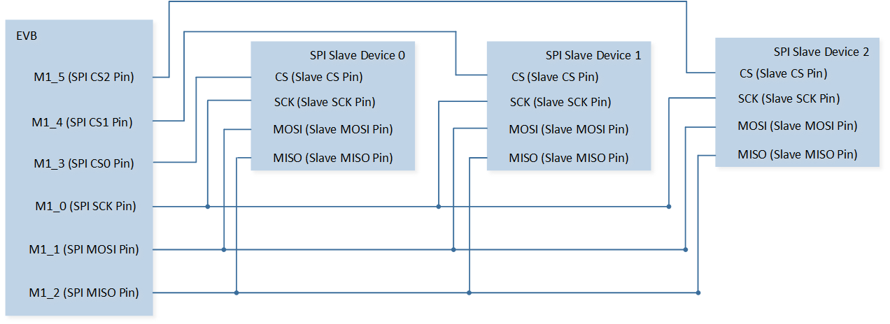
SPI Sample Code Hardware Connection Diagram
Configurations
-
The following macros can be configured to modify pin definitions.
#define PIN_SPI1_SCK P1_0#define PIN_SPI1_MOSI P1_1#define PIN_SPI1_MISO P1_2#define PIN_SPI1_CS0 P1_3#define PIN_SPI1_CS1 P1_4#define PIN_SPI1_CS2 P1_5
-
The entry function is as follows, call this function in
main()to run this sample code. For more details, please refer to the Initialization.spi_switchcs_demo();
Building and Downloading
For building and downloading, please refer to the Building and Downloading.
Experimental Verification
Press the Reset button on the EVB.
The data in array
SPI_WriteBufis sent to SPI slave device 0.Then the data in array
SPI_WriteBufis sent to SPI slave device 1.Then the data in array
SPI_WriteBufis sent to SPI slave device 2.
Code Overview
Source Code Directory
For project directory, please refer to Source Code Directory.
Source code directory:
sdk\src\sample\io_demo\spi\dynamic_switch_cs\spi_switchcs_demo.c.
Initialization Flow
The initialization flow for peripherals can refer to Initialization Flow.
SPI initialization flow is shown in the following figure.
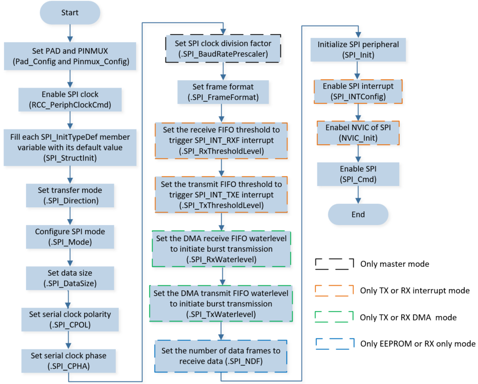
SPI Initialization Flow Chart
-
Call
Pad_Config()andPinmux_Config()to initialize the pins.static void board_spi_init(void) { Pinmux_Config(PIN_SPI1_SCK, SPI1_CLK_MASTER); Pinmux_Config(PIN_SPI1_MOSI, SPI1_MO_MASTER); Pinmux_Config(PIN_SPI1_MISO, SPI1_MI_MASTER); Pinmux_Config(PIN_SPI1_CS0, SPI1_SS_N_0_MASTER); Pinmux_Config(PIN_SPI1_CS1, SPI1_SS_N_1_MASTER); Pinmux_Config(PIN_SPI1_CS2, SPI1_SS_N_2_MASTER); Pad_Config(PIN_SPI1_SCK, PAD_PINMUX_MODE, PAD_IS_PWRON, PAD_PULL_NONE, PAD_OUT_ENABLE, PAD_OUT_HIGH); Pad_Config(PIN_SPI1_MOSI, PAD_PINMUX_MODE, PAD_IS_PWRON, PAD_PULL_NONE, PAD_OUT_ENABLE, PAD_OUT_HIGH); Pad_Config(PIN_SPI1_MISO, PAD_PINMUX_MODE, PAD_IS_PWRON, PAD_PULL_NONE, PAD_OUT_ENABLE, PAD_OUT_HIGH); Pad_Config(PIN_SPI1_CS0, PAD_PINMUX_MODE, PAD_IS_PWRON, PAD_PULL_NONE, PAD_OUT_ENABLE, PAD_OUT_HIGH); Pad_Config(PIN_SPI1_CS1, PAD_PINMUX_MODE, PAD_IS_PWRON, PAD_PULL_NONE, PAD_OUT_ENABLE, PAD_OUT_HIGH); Pad_Config(PIN_SPI1_CS2, PAD_PINMUX_MODE, PAD_IS_PWRON, PAD_PULL_NONE, PAD_OUT_ENABLE, PAD_OUT_HIGH); }
Call
RCC_PeriphClockCmd()to enable the SPI clock and function.-
Initialize the SPI peripheral:
Define the
SPI_InitTypeDeftypeSPI_InitStructure, and callSPI_StructInit()to pre-fillSPI_InitStructurewith default values.Modify the
SPI_InitStructureparameters as needed. The SPI initialization parameter configuration is shown in the table below.Call
SPI_Init()to initialize the SPI peripheral.
SPI Initialization Parameters SPI Hardware Parameters
Setting in the
SPI_InitStructureSPI
Direction
Device Role (SPI Master or SPI Slave)
Data Frame Size
Clock Polarity
Clock Phase
Clock Div
100
Frame Format
Call
SPI_Cmd()to enable SPI.
Functional Implementation
Master Send Data by Polling
Call
SPI_SendBuffer()to send the data inSPI_WriteBufto the slave.Call
SPI_GetFlagState()to checkSPI_FLAG_TFEandSPI_FLAG_BUSYflag state, and wait for the SPI data transfer to complete.Call
SPI_SetCSNumber()to switch slave device.
uint8_t SPI_WriteBuf[3] = {0x01, 0x02, 0x03};

SPI_SendBuffer(SPI1, SPI_WriteBuf, 3);

/* wait TX FIFO empty */
while (SPI_GetFlagState(SPI1, SPI_FLAG_TFE) == RESET);
while (SPI_GetFlagState(SPI1, SPI_FLAG_BUSY));

SPI_SetCSNumber(SPI1, 1);